How To Dimension Cross Break Sheet Metal

X pro cad consulting 3 723 views.
How to dimension cross break sheet metal. Cross break light bends added to sheet metal in order to stiffen its surface. 159 solidworks sheet metal tutorial cross break reason real examples single and multiple faces 4 duration. A cross break in sheet metal is when multiple obtuse bend angles of approximately 170 are made across a flat section thin metal. Cross braking is a technique performed using a press brake.
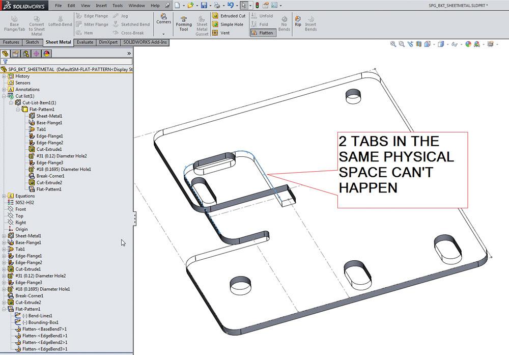
The dimensions of a part with a cross break are not changed. Cross breaks are most commonly in an x shape forming a slight pyramid shape in the metal without overly distorting it. You can edit the cross break sketch to move corners and change relationships. Since each metal fabricator has its own tooling bend factors and equipment to develop the flat blank it is better to fully dimension to formed views for that manufacturer.
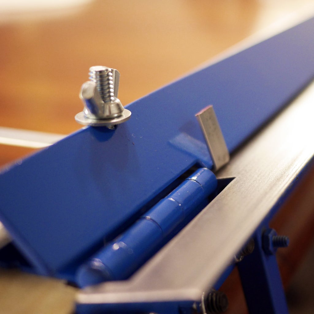
We used the following equipment to produce this video. Bar fold http amzn to 2ebbi4w samsung note 2 i show you how to get a cross break in sheet metal with. When you create a drawing of a sheet metal part with a cross break the flattened view is labeled with the bend direction bend radius and bend angle. Crowning the deflection along a bend due to the tooling or brake not being able to apply equal tonnage along the bend.
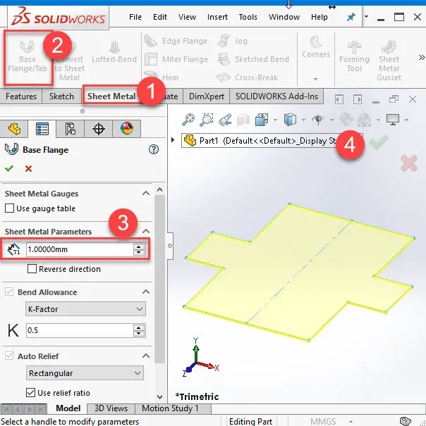
The crossing ridges stiffen the face of the metal and help prevent is from buckling under a load. A second bend is made across this initial one leaving an x impression on the sheet. A question we sometimes get in the solidworks sheet metal course is how to insert a 3d cross break. Your manufacturer may not be able to match dimensions when creating the actual sheet metal part due to tooling and equipment limitations.
To form the operator marks the bend line on the sheet as a guide then lines it up with punch tip and performs a shallow bend.

